Technical Brief: FCW-05
Custom Icons in FastCAD 32
by Dan Ichikawa
September 18, 1997
Introduction
One of the features that makes FastCAD 32 so easy to use is the ability to customize the toolbar icons. This means more than simply toggling toolbars on or off. FastCAD 32 lets you create your own icons and assign whatever functionality you want to them. In this article, we'll discuss how to create a custom icon and how to implement it.
Creating a Custom Icon
You can use the Microsoft Paint program that ships with Windows 95 to create a custom icon. You can use any graphics package, but Paint has all the features you would typically need to create a functional graphic.
An icon is simply a 16x16 bitmap file. 16x16 means that the graphic's size is sixteen pixels in both the horizontal and vertical directions. A bitmap file is a standard graphic format. The Paint program can save anything you create as a bitmap file.
Open the Paint program by clicking the Start button, then selecting Programs > Accessories > Paint.
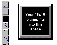
 To create a 16x16 image, select Image > Attributes from the Paint menu bar. You'll see a dialog box titled "Attributes". First, set the Units to Pels, then set both the Width and Height to 16. You should also make sure that Colors is checked. Then choose the OK button to accept the settings and close the dialog box. The drawing "canvas" shrinks to a tiny white box. To magnify the image, click on the magnifying glass icon and choose the "8x" option that appears in the bottom left portion of the screen.
When you create your icon, you do not have to worry about the 3D raised appearance or the button border. The bitmap graphic you create will appear to be pasted on top of the button within the border.
Start creating your icon by first determining its background color. If you wish your icon to seamlessly blend with the button, go to the Paint palette and choose the gray color next to the white color and paint the blank canvas with this gray. Unless you have customized your system colors, this gray corresponds to the gray FastCAD 32 uses.
Now go ahead and create your icon using the editing tools provided with the Paint program. Be sure to save it as a .bmp file. Save the file or copy it to your FastCAD 32 working directory.
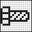
 EXAMPLE: Try drawing the pictured icon of a bolt in Paint and save it as iconbolt.bmp in the FCAD32 folder:
Adding Your Custom Icon to an Icon Bar
All icon bars in FastCAD 32 are defined in the file fcw32.imn, located in your working FastCAD 32 folder. It is a regular ASCII text file, and you can edit or view it using the notepad program that ships with Windows 95. You can use Wordpad or another word processor, but if you make changes you must be sure to save your file in plain text format.
If you examine the fcw32.imn file, you will see that each line follows a set pattern:
#n,ICONNAME:[Tooltip Text]|COMMAND;
n denotes the vertical position of the icon within an icon bar. The following position ranges are assigned to each icon bar:
| Starting from: |
Ending at: |
Icon Bar |
| 0 |
47 |
Standard Icon Bar |
| 100 |
147 |
3D Icons |
| 200 |
247 |
Left Custom Icon Bar |
| 300 |
347 |
Draw Icons Bar |
For instance, an icon with the position 300 will appear at the top of the Draw Icons Bar. An icon at position 302 will appear third from the top, on the Draw Icons Bar.
ICONNAME is the name of the icon file. You must include the .bmp file extension. The default icons in the fcw32.imn do not have extensions because those icons are embedded in the program. Follow the file name with a colon.
Tooltip Text is the text you want to appear in the little yellow box when you drag your mouse across the icon. The Tooltip text must be enclosed in [square brackets].
COMMAND is the FastCAD 32 function the icon performs. You may include other parameters on this line — FastCAD will process each instruction on the line until it reaches the carriage return. The command can consist of a regular built-in FastCAD command, or it can reference a macro command you may have created.
The other special characters serve a purpose too. The "#" character must appear before the icon position reference. The "|" vertical bar character cancels any command that might be active at the time the icon is pressed. Typically, the "|" is only omitted for "transparent" commands such as the zoom variants. The line must end in semi-colon, which also acts as a right-click or enter. You can use multiple semi-colons to simulate acceptance of default/prior values in a command prompt sequence. Be sure that you do not end any line with trailing spaces as these will be misinterpreted as auto-repeats.
EXAMPLE: Let's try applying the bolt icon you created above. We'll use it to insert a part.
In case you're not familiar with the concept, parts are simply FastCAD drawing files on your hard drive that you combine with your current drawing. For instance, you might have a drawing that consists of nothing but a title block. You can insert the title block drawing into your current drawing rather than drawing it again from scratch. Please see the FastCAD 32 manual or on-line help facility for more information on parts.
Ideally, the icon should match the drawing, so we'll try to use the bolt icon to insert a drawing of a bolt. If you own an older copy of FastCAD/EasyCAD DOS, or EasyCAD for Windows, convert the newbolt.fcd or newbolt.ecw drawing into the .fcw format and copy it into your working FastCAD directory. If you don't have the newbolt drawing, don't worry. In the instructions, just substitute the name of any other drawing for newbolt.fcw (it doesn't have to be a bolt), or create your own newbolt.fcw drawing (it doesn't matter how crude it is -- this is just an exercise!).
Now open the fcw32.imn file in a text editor such as Notepad. We will add the icon to the Left Custom Icon bar. We will add a new line to this file. FastCAD 32 doesn't care where you add the new line, but to keep things organized, it's best to determine where the icon will be placed, and then insert a new text line in the corresponding position within the existing text. If we reference the table above, we see that the icon position must be between #200 and #247, inclusive. Let's say we want the icon to appear below the existing Help icon (position #202), separated by a space. To create the space, we skip position #203 and use #204. So after the Help icon line, start a new line. So far we have:
	#202,HELP:[Help]HELPCON;
	#204,
The name of the icon we created is iconbolt.bmp and it is located in our FastCAD 32 directory, so we are set there:
#204,iconbolt.bmp:
For Tooltip text we'll simply use the word "bolt". We'll add the vertical bar to cancel any command that may be running when the bolt icon is clicked:
#204,iconbolt.bmp:[bolt]|
For the command, we'll use the built-in command PARTM, which inserts a part by filename. If you're using a file other than newbolt.fcw, substitute the different filename. We need to end the line with a semi-colon to act as a return on the filename as if we had typed it in at the "Command:" prompt:
#204,iconbolt.bmp:[bolt]|PARTM newbolt.fcw;
If we leave the command the way it is, we will manually have to hit the enter key (or right-click) to accept the scaling and rotation prompts that subsequently appear. We can bypass those steps by adding two semi-colons to the line:
#204,iconbolt.bmp:[bolt]|PARTM newbolt.fcw;;;
Now save the file and restart FastCAD 32. You may have to toggle on the Left Custom Icon Bar by using the Screen Tools command (click the hammer icon located on the Status Bar). Your new icon should be visible! Click on the icon and you should see the "Insert at:" prompt. Click anywhere on the screen and then right-click to terminate part insertion. If needed, use the Zoom Extents command or icon.
You can add or redesign as many icons as you can see on the screen. Make your CAD work easier by taking advantage of this customization feature whenever you feel it might help.
©1997 Evolution Computing, Inc.
 To create a 16x16 image, select Image > Attributes from the Paint menu bar. You'll see a dialog box titled "Attributes". First, set the Units to Pels, then set both the Width and Height to 16. You should also make sure that Colors is checked. Then choose the OK button to accept the settings and close the dialog box. The drawing "canvas" shrinks to a tiny white box. To magnify the image, click on the magnifying glass icon and choose the "8x" option that appears in the bottom left portion of the screen.
 EXAMPLE: Try drawing the pictured icon of a bolt in Paint and save it as iconbolt.bmp in the FCAD32 folder: